Build a Wi-Fi Lawn Sprinkler Controller
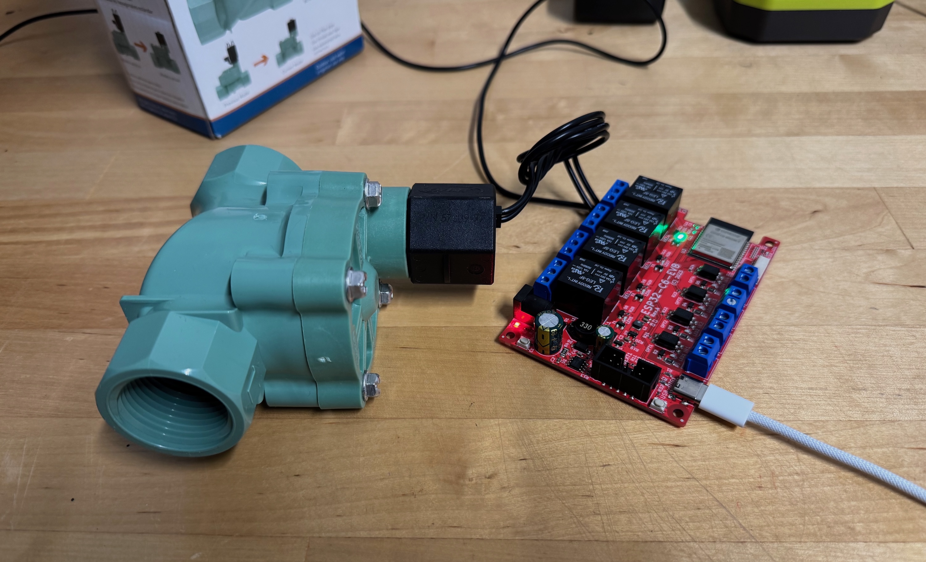
Take an off-the-shelf relay board, wire it to your existing 24 volt sprinkler valves, and generate a browser-based controller — per-zone manual control plus a weekly watering schedule — without hand-writing a single line of HTML.
The problem we're solving
A typical residential irrigation system is just a handful of solenoid valves buried in a box near the garden, each feeding one "zone" — the front lawn, the flower beds, the drip line along the fence. A traditional sprinkler timer is a closed appliance bolted to the garage wall: fiddly buttons, a dim LCD, and no way to trigger a zone from your phone when you notice a dry patch.
We can do better. Each valve is opened by sending 24 volts AC to its solenoid; cut the voltage and the valve springs shut. That's a perfect job for a relay. If we put four relays behind an ESP32 and give it a web page, we get a sprinkler controller we can reach from any browser on the home network — with a clean per-zone UI and a weekly schedule we design visually instead of coding by hand.
The board: Olimex ESP32-C6-EVB
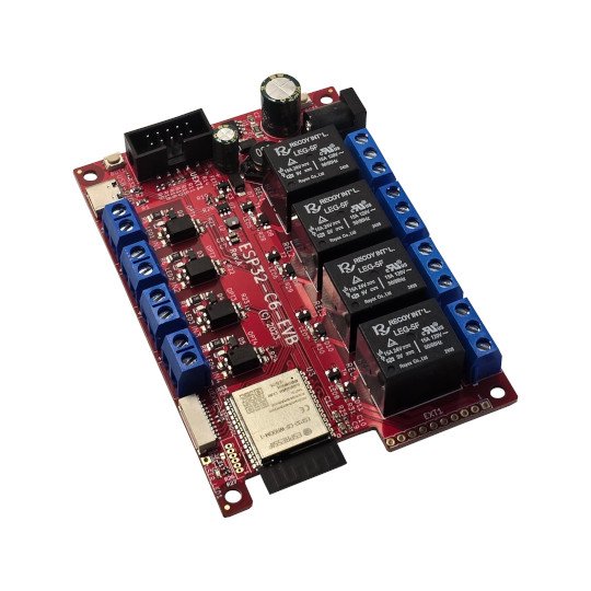
The Olimex ESP32-C6-EVB is an open-source-hardware evaluation board built around Espressif's ESP32-C6. It pairs the MCU with four onboard relays and four opto-isolated inputs, which is exactly the shape of a four-zone sprinkler controller — no relay HAT or breadboard wiring required.
Specifications that matter for this build
| Feature | Detail | Why it matters here |
|---|---|---|
| MCU / module | ESP32-C6-WROOM-1 (RISC-V, up to 160 MHz, 4 MB flash) | Runs the generated web server |
| Wireless | Wi-Fi 6 (2.4 GHz), Bluetooth 5 LE, 802.15.4 (Thread/Zigbee/Matter) | Serves the UI over your home Wi-Fi |
| Relays | 4×, rated 10 A / 240 VAC, dry contacts (NO/COM/NC) | One relay switches one sprinkler zone |
| Relay GPIOs | GPIO10, GPIO11, GPIO22, GPIO23 | The pins your UI toggles drive |
| Opto inputs | 4× isolated, 5–30 VDC (GPIO1/2/3/15) | Optional: rain sensor / flow switch |
| Power in | Barrel jack 8–50 VDC, or USB-C | Power from a small DC adapter |
| Programming | USB-C (also JTAG); ESP-PROG header | Flash straight from the browser |
| Size | 100 × 70 mm | Fits a small weatherproof enclosure |
The relay contacts are rated for up to 240 VAC, but our sprinkler valves are only 24 VAC — we're using a fraction of the relay's capability, which is exactly what you want for reliability.
How the pieces map to zones
The mental model is one-to-one: one relay = one zone = one valve, and each zone gets its own on/off toggle and its own weekly schedule. Each toggle drives the matching relay GPIO, which closes the relay contact, which sends 24 VAC to that valve's solenoid and opens the water.
| Zone | Example use | Relay | ESP32-C6 GPIO |
|---|---|---|---|
| Zone 1 | Front lawn | Relay 1 | GPIO10 |
| Zone 2 | Back lawn | Relay 2 | GPIO11 |
| Zone 3 | Flower beds | Relay 3 | GPIO22 |
| Zone 4 | Drip line | Relay 4 | GPIO23 |
Step 1 Wire the valves to the relays
Sprinkler valves use a common 24 VAC transformer. One
transformer wire is shared by every valve (the "common"); the other wire of each
valve is switched on and off — that's the job of the relay. Each relay gives you
three screw terminals: COM (common), NO (normally open),
and NC (normally closed). We use COM and NO
so the valve is off until the ESP32 energizes the relay.
COM; each relay NO goes to one valve; all valve returns join the transformer common.- Power off the transformer. Land the transformer's hot lead on a small
jumper bus feeding all four relay
COMterminals. - Run each relay's
NOterminal out to one valve wire (Zone 1 → Relay 1, and so on to match the table above). - Join every valve's other wire together with the transformer's common lead.
- Power the board itself from a separate 5 V USB-C supply (or an 8–50 VDC adapter on the barrel jack) — not from the 24 VAC sprinkler transformer.
Step 2 Describe it — let AI build the diagram
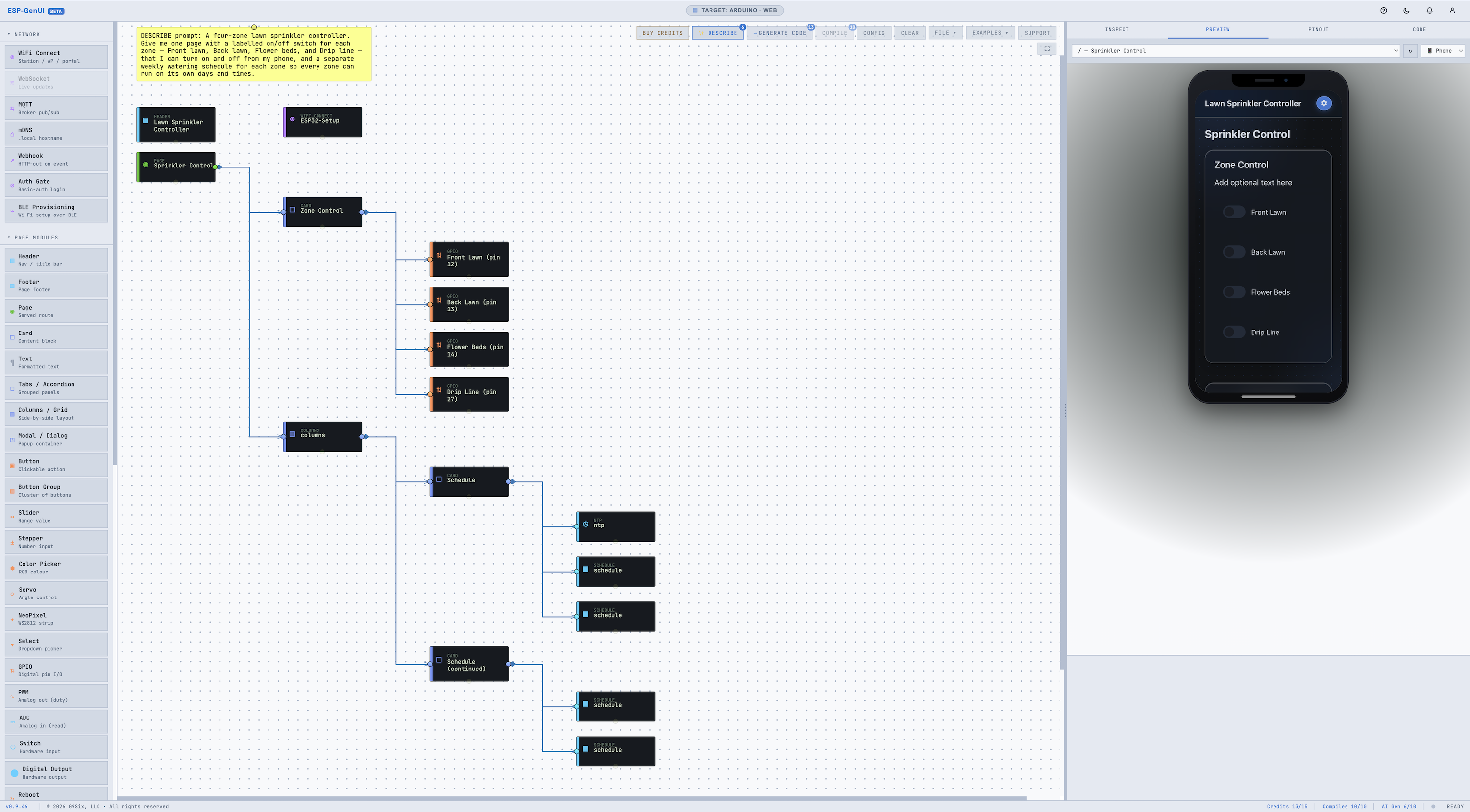
Open the editor. Instead of dragging modules onto the canvas one at a time, click ✨ Describe and tell it what you're building in plain English. The AI assembles the whole diagram for you — the page, the zone controls, the schedule, and the wiring between them — so you go from a sentence to a working starting point in one step. For this project, paste something like:
"A four-zone lawn sprinkler controller. Give me one page with a labeled on/off switch for each zone — Front lawn(gpio 10), Back lawn(gpio 11), Flower beds(gpio 22), and Drip line(gpio 23) — that I can turn on and off from my phone, and a separate weekly watering schedule for each zone so every zone can run on its own days and times."
Describe reads that and builds a matching diagram — typically a Page with a Header, four browser-controllable on/off GPIO toggles (one per zone, because a load you switch by hand is a GPIO output), a Schedule for each zone's weekly plan, and an NTP time source it wires in automatically so the schedules know the time. It often adds a WiFi Connect step too, so the board can join your network on first boot. That's the whole structure, generated for you. (If Describe starts you with a single shared schedule, add one per zone — Step 3 explains why that matters.)
Set the hardware specifics
Describe designs the interface, but it assigns placeholder pins that won't match your board — so finish the zones in the Inspector. Click each zone's GPIO node and set its pin to the matching relay (10, 11, 22, 23) and its active level to HIGH (the ESP32-C6-EVB relays energize on a HIGH). Each GPIO node already renders its own on/off toggle on the page, so manual per-zone control is done — no code required.
// gpio/Front Lawn). So label your zones clearly; that's how you'll
tell the generated functions apart when you fill them in in Step 3.Step 3 Add the watering logic in Callbacks.h
Because each zone is a GPIO node with its pin and active level set in the Inspector,
ESP-GenUI has already written the hard part. When you generate,
Callbacks.h comes pre-populated: a helper for every GPIO zone
and a pair of stubs for every Schedule. The on-page toggles already call the helpers,
so manual control needs no code at all — the only thing you fill in
is what each schedule should do.
onScheduleStart__9e6ea0b9_0086_…), and the rest of
the sketch calls it by that exact name. If you retype a stub with a friendlier name
of your own, the build fails with 'onScheduleStart_…' was not declared
in this scope. Fill in the bodies of the stubs already in the file
and leave their names exactly as generated.You don't need to memorize those ids — the generator tags each helper and stub
with a comment showing the node's label. Here's the shape of what's
in your Callbacks.h; find each zone by its // gpio/…
and // schedule/… comment and copy the real name from there:
// ---- Generated near the top: one helper per GPIO zone ---- // setGpio_<id>(true|false) — gpio/Front Lawn // setGpio_<id>(true|false) — gpio/Back Lawn // setGpio_<id>(true|false) — gpio/Flower Beds // setGpio_<id>(true|false) — gpio/Drip Line // (each <id> is that node's unique id — use the real names from your file) // ---- Fill in the BODY of each schedule stub (its name is already there) ---- // schedule/Front Lawn — open only the front lawn while its window runs. inline void onScheduleStart_<id>(int index, int duration) { allZonesOff(); setGpio_<id>(true); // gpio/Front Lawn } inline void onScheduleEnd_<id>(int index) { setGpio_<id>(false); // gpio/Front Lawn } // Repeat the same three lines in the schedule/Back Lawn, schedule/Flower Beds // and schedule/Drip Line stubs — each opening its own zone.
onScheduleLoad_<id>() and
onScheduleChanged_<id>() for each Schedule (plus a matching pair
for the pause switch), already filled in. Their default bodies persist the entry
list to flash (NVS) with the Preferences library — which
ESP-GenUI includes for you — so the watering times you set aren't lost on a
power cut. Leave them as-is unless you'd rather store the schedule elsewhere (an SD
card, LittleFS, a cloud sync).index), which
breaks the moment a zone needs two watering windows or you reorder them. Giving
each zone its own Schedule sidesteps that entirely: the callback identity
is the zone.setGpio_* helpers stay
logical — true always means the valve is open. If a relay
clicks on at boot, flip that node's active level; you never hand-edit pin logic.Because this file is yours, your edits survive a regenerate: tweak the diagram and generate again, and ESP-GenUI rewrites the site files but merges your callbacks instead of overwriting them.
Step 4 Generate, compile & flash
- Click Generate Code. You'll get a complete Arduino sketch —
demo.ino,EmbeddedSite.h, and your editedCallbacks.h. - Plug the board into your computer with USB-C. In a Chromium-based browser (Chrome or Edge), click Compile: in the dialog, Auto Detect Board reads the chip and picks the board, Compile builds it server-side, and Flash to Device writes it over Web Serial — no local Arduino IDE needed.
- Prefer your own toolchain? Use Download ZIP, or — on
Chrome/Edge — Save to Folder, which writes the sketch
straight into a folder on disk (no ZIP to unzip) and remembers it, so the Arduino
IDE, PlatformIO, or VS Code picks the files up in place each time you regenerate.
Either way, select an ESP32-C6 board target. Save to Folder is the
fastest loop for this path — when a folder is attached, ESP-GenUI can even
run the Diff/Merge automatically on the next save so your
Callbacks.hedits are preserved.
'onScheduleStart_…' was not declared in
this scope? This means a schedule (or GPIO) stub in
Callbacks.h was renamed or rewritten, so its name no longer matches
what the rest of the sketch calls — usually from typing your own function
name instead of editing the generated one. To recover:
- Regenerate
Callbacks.h(Generate Code again, or accept ESP-GenUI's stubs in the Save-to-Folder Diff/Merge). This restores every stub with its correct generated name. - Move your logic into the stub bodies — find each
// schedule/…stub and fill in its body as in Step 3, calling the// gpio/…helper by the exact name from the file. Delete any leftover functions you'd named yourself. - Compile again. The generated caller now finds every stub.
Step 5 Test and schedule
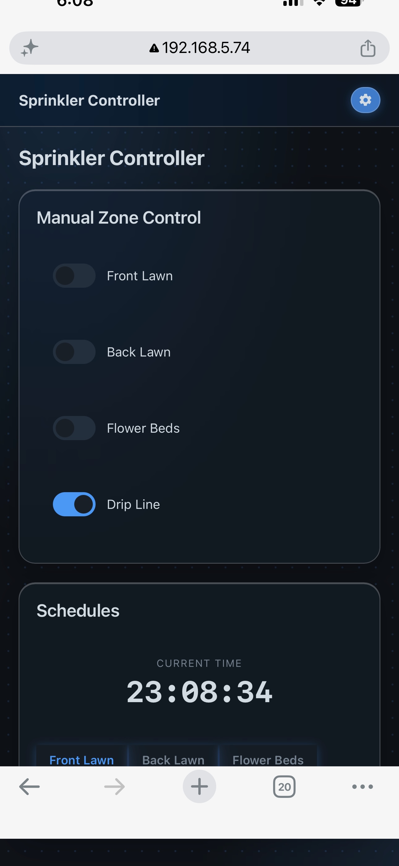
After flashing, the board joins your Wi-Fi and serves the page at its IP address
(or its .local name if you added an mDNS node). Open it from a browser
on the same network and:
- Bench-test first, dry. Before trusting the valves, toggle each zone and listen for the relay click and its status LED — confirm Zone 1 drives Relay 1, and so on.
- Test with water. Turn on the transformer and toggle one zone; you should hear the valve open and see that zone water. Toggle it off and confirm it closes.
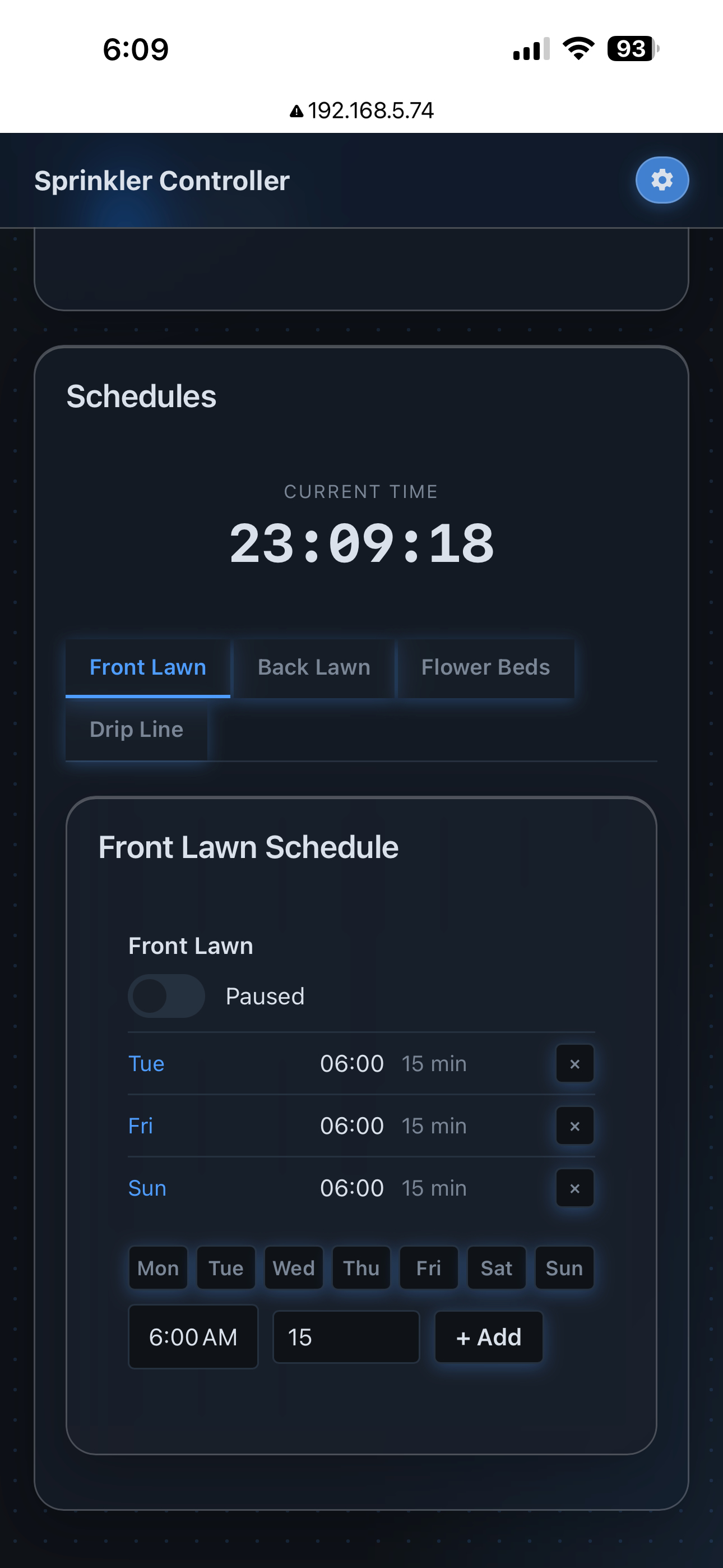
- Set each zone's schedule. Open a zone's Schedule and add its watering windows (e.g. 6:00 AM Mon/Wed/Fri for 10 minutes). Because each schedule drives just one valve, every zone keeps its own independent days and times — and a zone can have as many windows as you like. The NTP node keeps the clock accurate so windows fire on time.
Where to take it next
- Rain skip. Wire a rain sensor to one of the opto-isolated inputs
(
GPIO1/2/3/15) and skip a scheduled run when it's wet. - Flow feedback. Add a flow switch to another input to detect a zone that isn't actually flowing (a stuck valve or a burst line).
- Notifications. Drop in a Webhook node to ping your phone when a watering cycle starts or finishes.
- Remote access. Add the Auth Gate node so the page asks for a username and password before anyone can trigger a zone.
That's the pattern for every guide here: pick real hardware, wire it, sketch the interface, map a few callbacks, and flash.